Powering on a Desktop Computer Remotely With a Raspberry Pi
I access my primary computer remotely for various reasons.
Take playing video games using Steam Remote Play, for example. I have a Windows virtual machine with a GPU passed through. With Steam running on it, I can connect from my phone, my laptop, or any device with the Steam Link app and play remotely. For games that are not on Steam, I can use Moonlight.
But imagine the frustration when the computer is not powered on, and I am not at home. Only a fellow video gamer may understand it.
And I don’t want to keep my computer running all the time.
Wake-on-LAN could be an option. But that works only when the computer is suspended and connected to the network through Ethernet.
And in a country where a power outage is a citizen’s right, relying on the computer staying suspended is silly.
Tinkering with a Raspberry Pi seemed like a reasonable way to solve my problem.
Parts Needed

I needed the following parts:
- A Raspberry Pi (Zero W) with the GPIO headers installed
- A 5V 2-channel relay
- Wires (terminated with Dupont connectors)
You can use any Raspberry Pi board as long as you can access it over the network.
Setting It Up
You will have to set up the Raspberry Pi with an operating system of your choice. What matters here is that you can interact with the GPIO pins.
If you are unsure you could install DietPi and then install WiringPi using DietPi’s software installer.
# dietpi-software
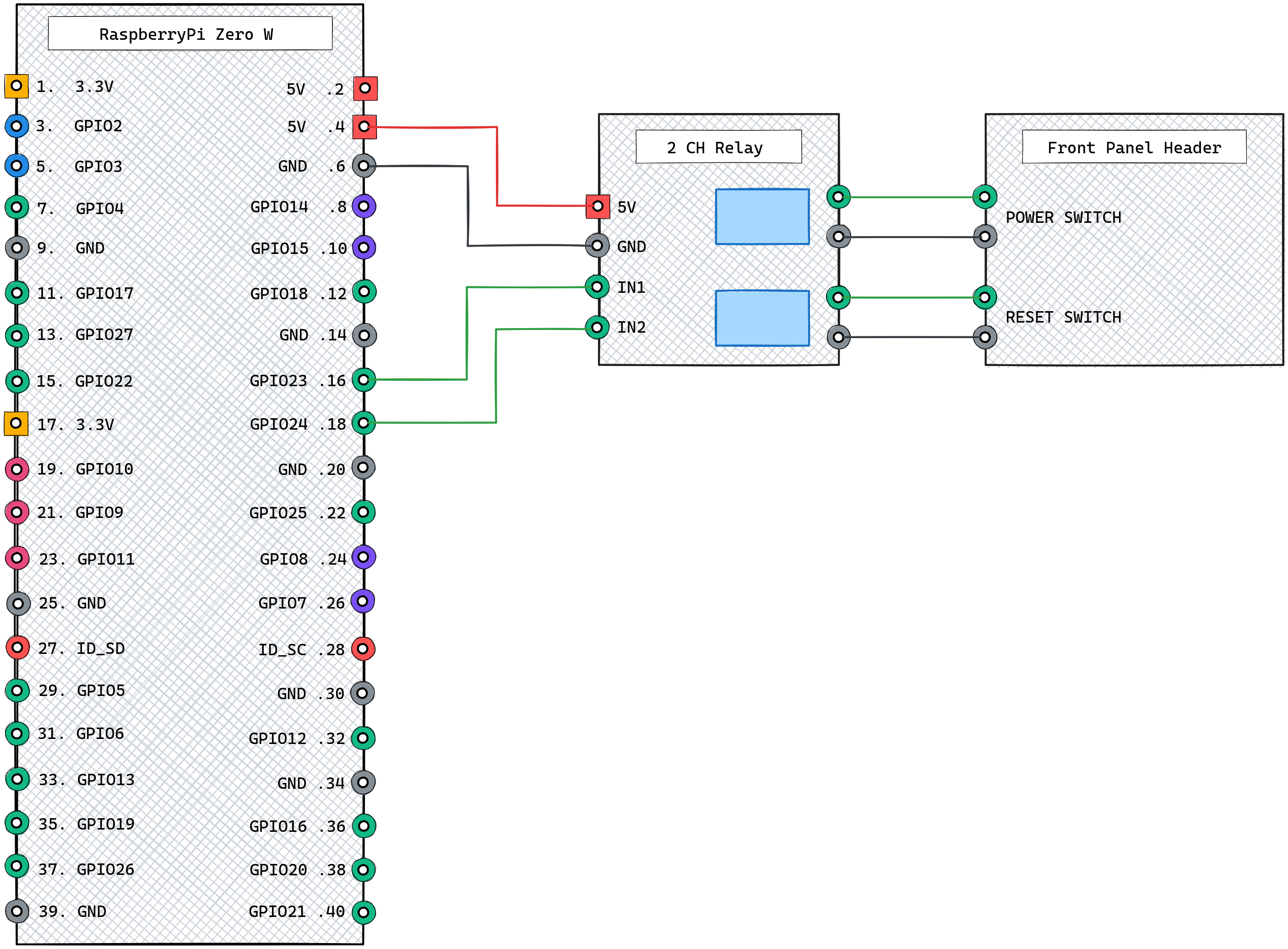
Next, connect the wires between the Raspberry Pi and the 5V relay.
You can tap 5V from the GPIO pins, only if you are powering the Raspberry Pi itself through the GPIO pins. In my experiments with a Raspberry Pi Zero W, I could not get the GPIO pins to provide enough current (for the relay) when powering the Raspberry Pi using a power adapter.
Make sure that you have connected 5V and GND to the relay and then connected two of the GPIO 1-26 pins.
Testing the Relay
Before wiring the relay to the computer, you can test things out.
Let’s assume you have connected one of the relay input pins to GPIO 4.
Access the Raspberry Pi directly or over the network (using SSH). Then run the following commands:
# gpio mode 4 out; gpio write 4 1
This command will set the GPIO 4 pin to output mode and set its value to 1.
Next, run this:
# gpio write 4 0; sleep 1; gpio write 4 1
You should hear the relay make a clicking sound, wait for a second, and make a clicking sound again.
That is what is going to be the power switch for the computer.
Connect the Relay to the Computer
Take two wires terminated with Dupont connectors on one end and screw the unterminated ends into the relay. Connect the Dupont connectors to the power switch pins on the computer motherboard’s front panel header.
Now, with the computer turned off, run the gpio commands again:
# gpio write 4 0; sleep 1; gpio write 4 1
You will hear a pair of clicks again, but this time, the computer should also turn on.
You can repeat the same process to wire the relay to the reset switch pins on the computer motherboard’s front panel header.
Wrap Up
It is possible to write a small program in one of your favourite programming languages (which should be Go, by the way) instead of using the command line.
I have a small program that exposes a web server to the local network, which I can use to trigger the GPIO pins and turn my computer on.
On the webpage that it serves, I have a button that triggers the power switch for half a second (to turn on the computer), a button for the reset switch, and a button that holds the power switch for five seconds (to force turn off the computer).
This post is 75th of my #100DaysToOffload challenge. Want to get involved? Find out more at 100daystooffload.com.
comments powered by Disqus